Google Pixel Stand Teardown
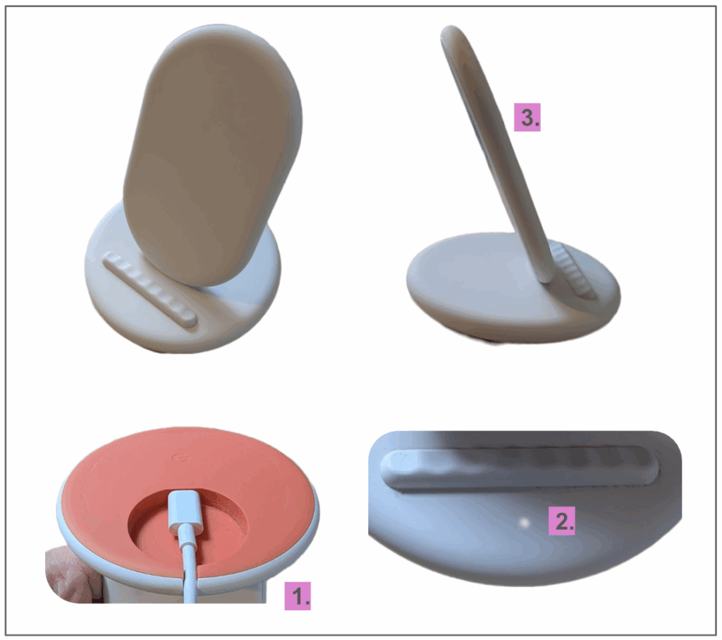
For our latest teardown, I chose the Google Pixel Stand, a Qi-compatible wireless phone charger. It’s covered in soft-touch rubber and has a two-tone bottom housing with a really clever recessed USB port and small notch for clean wire routing (1).
A single status LED shines through the rubber surface of the charger when charging starts (2). It’s very elegant, not harsh or obtrusive like other LEDs I’ve seen. My guess is that the rubber helps to diffuse light.
The support for the phone feels very robust but it’s only 9 mm thick (3). The charger is pretty heavy as well, which helps prevent it from sliding around on a table. My suspicion is we’ll find some metal parts in here contributing to the stiffness and weight. Let’s tear it down and find out!
Getting inside
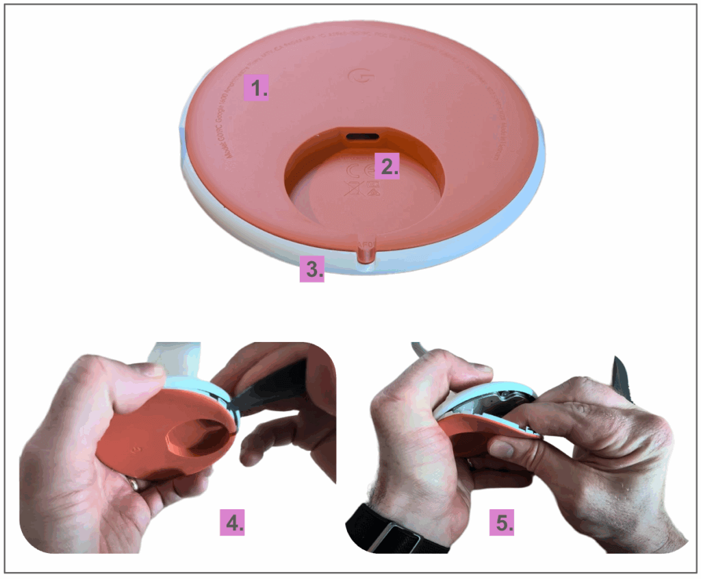
I really like the bottom of this charger! All of the regulatory information is elegantly embossed into the rubber (1), and the Google “G” logo sits prominently in the middle. A recessed circle (2) provides just enough clearance for fingers while plugging in a USB-C cable, and the “mouse hole” notch for the cable routing is is a great touch (3).
Slipping a spudger between the top and bottom housings and prying gently helps to separate the two parts from each other (4), but I had to pull pretty hard to separate the two housings due to some tape used to keep the parts together (5)
I try and avoid tapes where possible because they complicate assembly and disassembly, but I think the tape here is used to prevent rattling and ensure the two housings feel solid when assembled. I’ll allow it this time 🙂
Bottom housing
The bottom housing is a double-shot plastic part. It’s first injection-molded in a rigid plastic (likely ABS), then moved to a second portion of the mold where rubber (likely TPE) is molded around it. Double-shot plastic parts are more expensive to manufacture and can’t be recycled, but they do allow for more premium surface finishes like soft-touch rubber and multiple colors.
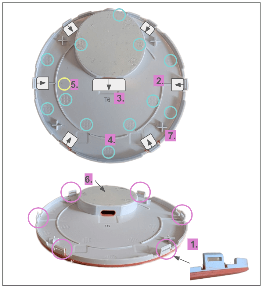
Six snap hooks are equally spaced around the perimeter of the bottom housing (1), and are used to engage with corresponding features in the top housing. These hooks are formed using lifters in the mold — metal components that can slide and lift out of the way during the molding process (2). They allow for more complicated geometry to be formed in the plastic parts, but increase the cost to make the tooling. Another lifter is used to form the hole for the USB-C port. (3)
Many ejector pin marks are also visible across this surface (4). These are used to push the plastic part out of the mold and are uniformly distributed around the part to prevent warping. The rigid plastic is injected into the mold at the gate, which leaves a small pockmark (5). I couldn’t find the gate for the rubber.
The top surface of the housing has a thin pressure sensitive adhesive applied (6). My guess is that there is a production line fixture to apply this consistently during assembly. Four X-shaped protrusions (6) touch off on the PCBA screws after being installed.
Bottom housing removed
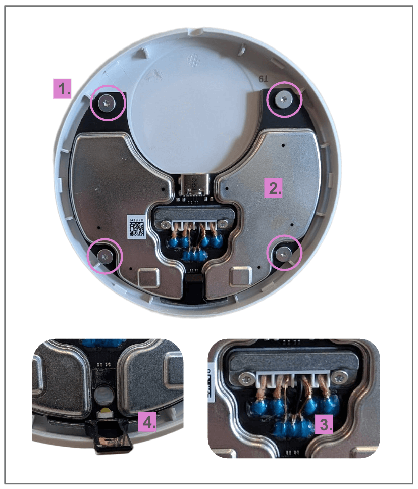
With the bottom housing removed, we can get a clear look at the electronics at play here. Four screws hold the PCBA to the top housing (1), and a metal part seems to be sandwiched in between.
Two large shields are soldered over the majority of the components on the circuit board (2). This is to prevent any electromagnetic interference (EMI) and is standard issue for parts that may emit more radio frequency “noise” than is permitted by the FCC. My guess is that the charging circuitry is to blame here.
There is a slot in the middle of the board where wires pass through and are soldered in place (3). There are four large wires and four small ones. The Pixel Stand has two charging coils, which explains the two sets of big cables!
I tend to try and avoid soldering on the production line, but according to a few electrical engineers, charging coils are more sensitive to impedance changes and soldering is recommended.
A small rubber boot covers the status LED and light pipe (4).
Charger assembly removed
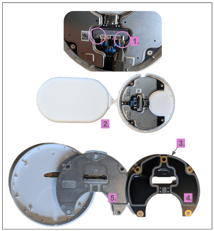
In order to keep tearing down this charger, I was forced to snip all the soldered wires. Two screws (1) hold the charger assembly to the base, and after removing them, I was able to slide it free (2)
The charger PCBA was also able to come free from the top housing. Some gentle prying between a die cast part the PCBA reveals some RF shielding tape used to hold the two parts together (3).
The top side of the charger PCBA has very complicated taped off areas (4) . These areas match the shapes of the RF shielding cans on the other side of the PCBA, and the RF tape sits on very wide traces used for grounding.
The die-cast part (5) seems fairly heavy, making me think it could be a zinc aluminum alloy instead of regular aluminum. This part is adding structure, weight, and RF shielding. It’s a great design!
Die-cast parts are much more expensive than injection molded plastic parts, and require expensive post processing too. I use them only when absolutely necessary.
Cool feature: Light pipe
The status light on this charger is really subtle and minimal, and I really like it! Part of it has to do with the way the light is programmed to slowly fade on and off, but the rest has to do with the light diffusion and light pipe design.
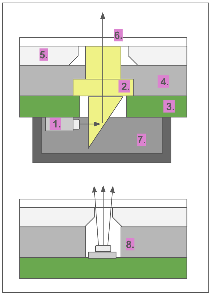
A light pipe is designed to help redirect the light from an LED and focus it into a particular area. In this case, a side-firing LED (1) and a prism on the light pipe (2) work together to create a point of light.
The light pipe runs through a hole in the PCBA (3) and in the die cast frame (4). The top housing is overmolded in TPE rubber with a hard plastic substrate (5) . A small area of just the rubber is used as the light diffuser itself (6).
A rubber cover prevents stray light from being visible in other areas (7) .
A far simpler design would’ve been to simply place a top-firing LED on the backside of the PCBA and shoot it at the rubber (8). The result would’ve been less elegant and would require adding components on the backside of the PCBA, but it would save two parts. Tradeoffs!
Charger disassembly
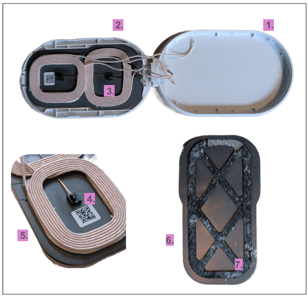
The charger unit has an overmolded rubber front housing (1) and a hard plastic rear housing (2). Like the base, they’re held together with snap hooks. Prying the hooks apart is pretty easy and the rear casing hinges open.
Inside, we have a charger subassembly. This is comprised of two charger coils (3) and two temperature sensors (4). I suspect thermistors are being used to monitor the temperature of each coil to throttle or stop charging if things get too hot.
The coils are adhered to a ferrite plate (5.) , which is adhered to a stamped metal plate (6.). This entire assembly is then adhered to the rear housing of the charger. That’s a lot of adhesives! Interestingly, the adhesive holding this assembly to the rear housing has large triangular sections cut out (7). I wonder if those pieces are used on other products.
The ferrite plate is used to help with EMI emission and ensure the charger works in the right direction. It’s very brittle and cracked easily when prying the assembly out of the rear casing. My guess is the metal plate is providing rigidity to this assembly, preventing the ferrite plate from cracking, and helps a bit with heat sinking.
The rear housing is pretty boring, in a good way! A few structural ribs and snap hooks and that’s about all.
Charger front housing
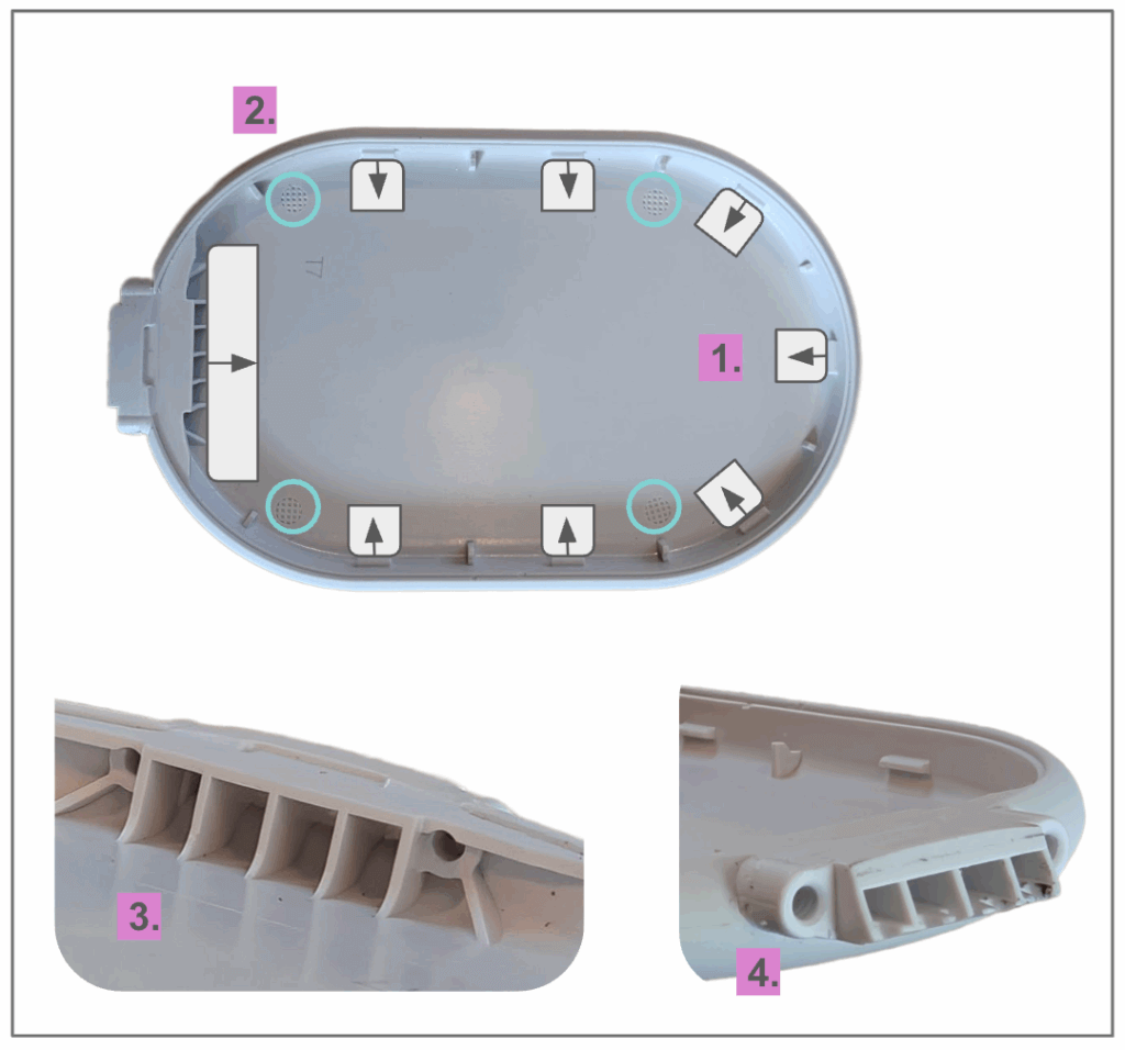
The front housing of the charger is a bit more exciting than the rear. It’s also a double-shot injection-molded part and has seven snap hooks equally spaced around the perimeter (1). These are molded using lifters. Four ejector pins are also visible inside (2).
There’s also a channel molded into the bottom section of the housing to route the cables from the charger and temperature sensors to the main circuit board (3). Two screw bosses molded into the outside of this channel are used to fasten the charger assembly to the die-cast plate (4).
Two long thread-forming screws are used to hold the plastic housing to the die-cast base. I love using these screws in my designs, as they self-thread into a plastic screw boss. This makes assembly easy and requires no post-processing to add threads or inserts. They’re excellent for designs when you’re not continuously installing and uninstalling something and they’re not subject to excessive vibration or thermal cycling.
My takeaways
This product is definitely a result of a strong industrial design-focused team. The construction, focus on soft touch plastics, and added metal parts for structure tell me that no expense was spared in making this product look and feel excellent.
I’m surprised by the sheer amount of EMI shielding in place here — the custom stamped covers, the EMI gasketing and die cast frame, and the ferrite sheet needed. Either this product had some issues during the prototype stage or they weren’t taking any risks and just went all in on EMI shielding.
The amount of adhesive used was also a shock to me. It was used between the parts on the base, to attach the PCBA to the die-cast frame, and for the entire wireless charger subassembly. I try and avoid adhesives where possible because they can be frustrating on an assembly line and make rework and repair difficult, but a good factory will be fine with it.
I think the light pipe was over-designed and added unnecessary parts and assembly steps that could’ve been replaced with a much simpler design. I’m curious how much worse it would look with a top-firing LED compared to the light pipe, rubber boot, and side-firing LED.
The soldered wires for the thermistor and the wireless charger, coupled with the design decisions made for the industrial design, mean that this device is trash if a part fails. The over-molded rubber also means it can’t be recycled. This is par for the course in most consumer electronics products these days, but a disappointment for sure.
informal is a freelance collective for the most talented independent professionals in hardware and hardtech. Whether you’re looking for a single contractor, a full-time employee, or an entire team of professionals to work on everything from product development to go-to-market, informal has the perfect collection of people for the job.