Why Onshape is my ride-or-die CAD tool
Ask any mechanical engineer what their CAD (computer-aided design) software of choice is, and they’ll probably have strong opinions. Many will say they prefer SolidWorks, mostly due to learning it in college and because their jobs use it. Apple alumnus will bring up NX, a very expensive and capable CAD program. Startups love Fusion360 for its low cost and integrated PCBA design programs. Some folks may even say they enjoy using CATIA or Inventor, but they’re wrong.
A new(ish) challenger in this world is Onshape, and it’s been my ride-or-die for the past 9 or so years, and I’ve been encountering more and more folks who use it as their primary CAD tool. I’ve used it to create complicated brain scanning headsets with flexible circuit boards inside, burrito holders that snap together without any screws, and — most importantly — my donut hole dispenser.
Recommending a new CAD tool to an engineer typically results in an eyeroll and some reply similar to “I don’t have time to learn something new.” Us engineers hate changes to our workflows, and change in general. Each CAD program has their own interface, terminology, and best practices that take hundreds of hours to refine and learn before you can feel as productive as you were in your previous program. The reasons to change have to be very compelling to make the jump. Lemme give it a shot.
What’s the big deal with CAD?
First off, let’s go over why these tools are important in the world of product design. CAD programs are complicated tools used to generate 3D models. Some of these programs excel at creating intricate surfaces and details, others are known for being excellent for designing massive and complex machinery, and others are best for video game character design. The CAD programs used by mechanical engineers are typically chosen because they are parametric — meaning they’re modeled step by step with commands and based on relationships to other parts of the 3D model.
Parametric modeling is a super cool concept that allows you to “program” geometry into a model. Shapes are drawn in 2D with relationships defined, like specifying that a horizontal line intersects a specific point or ensuring a spacing of 5 millimeters between lines. Mathematical equations can be used to create robust and complex relationships between the geometries, allowing you to equally space holes on a flat part or ensure a rib in an injection-molded housing is 60% of the thickness of the nominal wall.
If done correctly, you can create very robust 3D models that can change their shapes and sizes to allow for flexibility in your design, without taking tons of time to fix things later. Creating robust parametric 3D models requires some foresight into how a part may change in the future, what geometric relationships are important, and how much flexibility you think is appropriate. It’s generally not worth the additional time and effort to create the world’s most flexible 3D model if you have a good idea of the final shapes you’re looking for, but it’s absolutely worth a bit more time and effort to create a model that can grow and shrink within reason. Creating a robust and adaptable 3D model using these tools is an art form that gets perfected over years of work, as there are dozens of ways to make the same 3D models but no “right” way.
Like most things in engineering, getting good at something is about learning the fundamentals and the rules followed by learning which rules you can break (and when). CAD programs are no exception. Mechanical Engineers may spend the majority of their day in these CAD programs and there are even competitions on speed 3D modeling.
Why Onshape?
I started playing with Onshape about 10 years ago when it was still in early beta. It was rough. I was using Solidworks full time at my job, designing 3D printers for Makerbot, and the concept of cloud-based 3D programs were interesting but seemed too risky and immature. The tools offered in this beta were primitive and the user experience was still janky. Most engineers who saw the program dismissed it entirely.
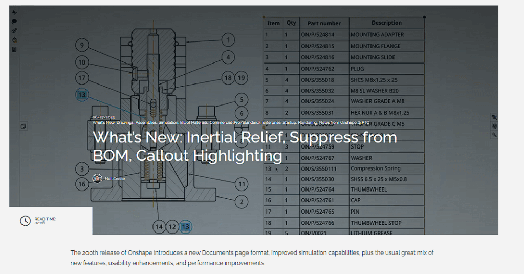
What if I needed to do CAD modeling offline? What if the internet went out? It couldn’t be as powerful as my $2500 laptop with a dedicated graphics card, right? It was a tough pitch, but the program was improving quickly and became more and more promising with each monthly release (seriously…they’ve exceeded 200 releases now)!
Then, in 2017 I started a new job and was forced to learn Creo. It wasn’t fun, and I felt like everything took four times longer. I was learning something new and was super inefficient in it. I nearly quit due to frustration but recommended we give Onshape a try again. I was hooked. I find that I’m significantly faster in Onshape than in Solidworks, mostly due the flexibility of the program and how I’ve been able to construct a workflow that works for me. I leverage the multibody modeling, robust variable tools, and mate connectors to move super quickly in CAD.
The best part for our team was the ability to collaborate in real time on parts like Google Doc. No saving, no crashing, no need for expensive file management tools. It worked similar enough to Solidworks that I was up and running in a few days. It wasn’t as feature-rich, but Onshape also provides meaningful updates nearly every 3 weeks. It was refreshing and fast! I’ve been using it as my daily driver ever since, and it’s only gotten better.
Most folks who have a negative reaction to Onshape usually are referring to the program that existed nearly a decade ago, and are unaware of the improvements made since then.
Using Onshape for the Donut Hole-der
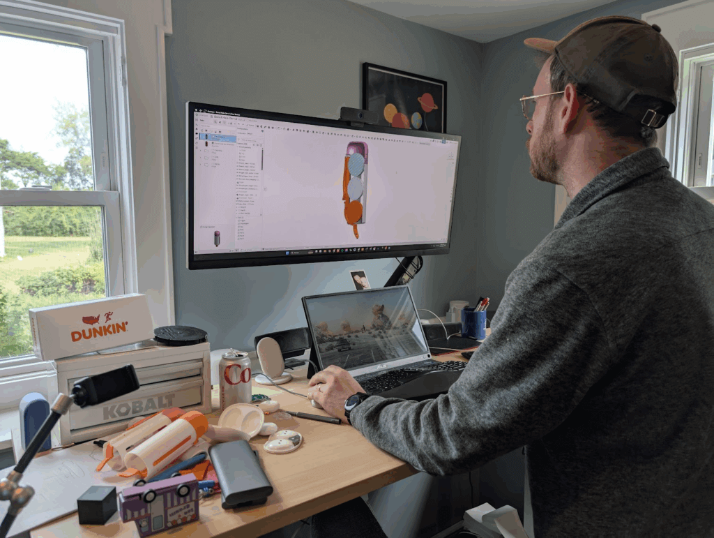
I’ve been using Onshape for the website design, product iteration, and patent application process for my Donut Hole-der over the last few months and thought it would be cool to peek behind the curtains a bit on my workflow and day-to-day use of the tool.
Revision controlling
Making hardware takes time, and requires many revisions until you arrive at the final design. I’ve created over 20 iterations of this Donut Hole-der, which involved tweaking the geometry of the dropstopper and trigger to hold a variety of different donut hole shapes and sizes, adding a flip top lid, and reducing the number of parts required.
I use my 3D printers to iterate in-house quickly, but keeping track of changes can get confusing. Progress is also not always linear during hardware design. It’s not uncommon to accidentally make things worse when trying to improve things, and reverting back to a previous version can get complicated. One way to mitigate this headache is to leverage the built-in revision control tools in Onshape to track each 3D-printed prototype I made.
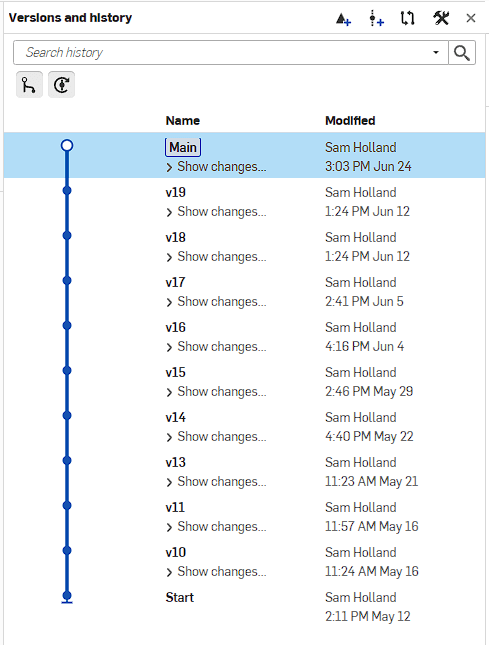
Onshape is cloud-based, and there’s no “save” command. Like Google Docs, each change is saved in real time. You can view a full changelog of each and every command, and revert back to them at any point. Onshape uses revisions as a way to bookmark a specific point in time, adding a name and details so they’re easy to remember. I try to remember to create a revision in Onshape every time I send something to my 3D printer. A quick note about what I’m testing helps as well, especially since my brain has been permanently fried during the last two years of fatherhood.
Onshape also has fancier release management capabilities, similar to other CAD programs, but that’s a whole other topic.
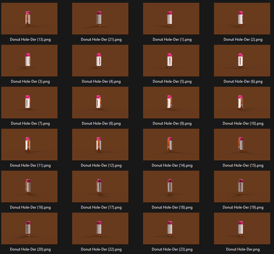
Rendering and animating
No website is complete without a fancy animation! Unfortunately, I lack the tools and knowledge to use high-end rendering or animation programs like Keyshot. Instead, I relied on the built-in render tools in Onshape to apply appearances and materials to each component. I did have to adjust the scaling and texture strength to best match my target materials, but I was generally very happy with the results of the renders I got out of it!
Onshape doesn’t have animation tools in the Render Studio, and I wanted a revolving animation of the product, so I had to get creative. I rendered out each and every angle as keyframes. Then, I stitched together all these renders into a GIF. Adjusting the framerate and time on each image helped to smooth out the animation so it looks a bit nicer. It’s no Keyshot, but it does the job for me! I’d love to see simple animation tools added to the render studio so I could generate these videos without me needing to hand-build them. Even better would be to allow animations of my assembly so I can show things rotating or opening.
Patent application
I’ve been listed as an inventor on a handful of patents in the past, but have never patented my own thing before. I was very excited to learn more about the process and help where I could! I worked with Keeley DeAngelo on this application process and used Onshape to help create the line art used for the design patent. Adjusting the line weight, cross hatching styles, and generating custom views allowed me to create a DXF file of all the desired angles and detail views the team needed. They imported these images into Adobe Illustrator to add additional lines to highlight surface curvature and tweak some weights to make it look just right.
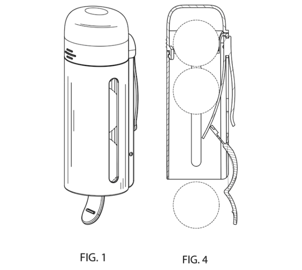
Overall, this process felt very smooth! It would be interesting to add a new visual mode for drawings that highlights surface curvatures with vertical lines to reduce the extra steps needed to make these images.
Design for manufacturing (DFM)
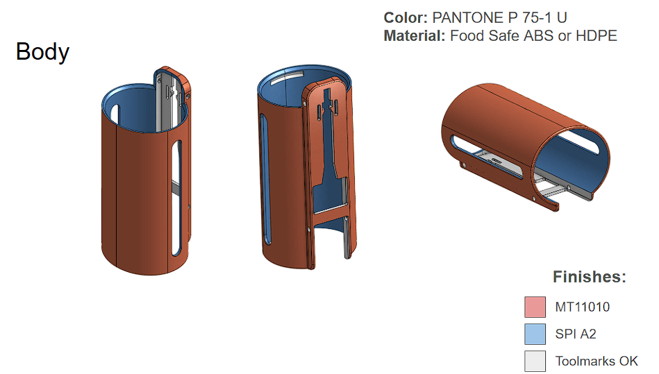
Just because you can make something in CAD doesn’t mean you can make it in real life! This is where DFM experience comes into play. Each manufacturing process has their own rules and best practices to create low-cost, high-quality, repeatable parts. Typically, the DFM process involved identifying vendors and working with them to resolve any issues with the part design in a series of review processes. To help communicate the intended design, I like to color-code my parts. For the Donut Hole-der, each color used represents where I think the components of an injection mold will meet together.
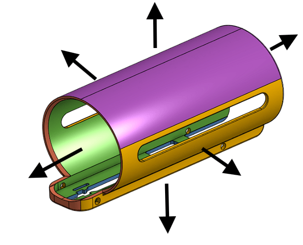
I also utilize colored faces to help convey which components require textures, which impact the mold tooling design and rules.
Later, I create dimensioned 2D drawings of each component with critical dimensions and inspection locations called out for our vendors to use as a guideline for manufacturing each part. These 2D drawings are essentially contracts between a client and a vendor, guaranteeing that the received parts will be within agreed-upon tolerances and specifications.
Getting started in Onshape
If you’re Onshape curious, I recommend getting a free trial and playing around. There’s always a learning curve with software, and it may take a few hours before you get your feet underneath you, but it’s really not bad! Here are five tips and tricks I think are important:
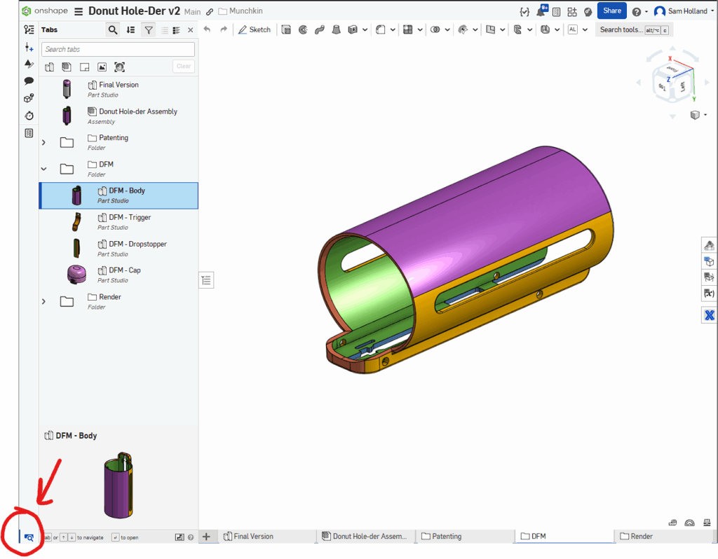
1. Pro tip: use the tab manager (ignore the bottom “ribbon” interface entirely).
Use the tab manager instead. You can open the tab manager by clicking the small magnifying glass icon in the bottom-left corner or by pressing Alt + T. Keep this side tab open to better navigate in documents. It’s the first thing I prefer and recommend, and I wish it was the default interface option.
2. Get familiar with the terminology.
Most CAD tools use similar terminology, but with a few tweaks here and there, just enough to get confusing. A few important ones to know in Onshape:
- Extrude/Revolve/Loft are used for both adding and removing material. It’s super handy once you get it.
- Derive is essentially “mport.” It’s crazy powerful and allows you to pull drawings and parts between Onshape documents or just between part studios. It allows for some amazing top-down modeling techniques.
- Boolean allows you to remove intersecting geometry between parts, or to fuse them together.
When in doubt, you can also use the search box to try and find the name of the feature in your legacy CAD program!
3. Learn to love multi-body modeling.
Onshape is amazing at multi-body modeling. In many programs, you create individual parts or bodies in separate files, then combine them together into assemblies. Multi-body modeling allows you to create multiple bodies.
I use multi-body modeling when creating components that have strong interdependencies with each other. It can be difficult to know when to create a new part versus when to continue modeling things in one studio. My rule of thumb is only do it when absolutely necessary, but I still violate this rule often. The downside of multi-body modeling is that it can become harder to make changes to your files later without causing potential problems with other parts. It’s all a balance.
4. Understand the power of mate connectors.
Mate connectors are a unique concept in Onshape to help make constraining parts and moving things easier. In traditional CAD programs, you need to define how parts relate to each other using mates. These may allow for specific degrees of freedom between parts, like a rotation mate or sliding mate, or they may connect parts together to always be parallel to each other. They can get complicated to define correctly and be fragile, breaking easily if parts are moved beyond limits.
Onshape simplifies this by generating coordinate systems in relation to any piece of geometry in your model. Their mates are super robust and powerful and can replace multiple constraints with a single, more complex relationship. I use mate connections to rapidly create assemblies and for generating reference geometry when importing and patterning parts.
5. Learn how to derive and translate.
One of the most powerful and confusing tools in Onshape is the Derive tool. I create common part libraries for things like screws, screens, and batteries, and then pull them into my current project using this Derive tool. I can then use the translate commands to precisely move these parts into position and then model around them. After you do this a few times, it becomes second nature and it’s a game changer.
If you’re ever curious, please don’t hesitate to reach out to me and I’ll talk your ear off about all these tools and more!
informal is a freelance collective for the most talented independent professionals in hardware and hardtech. Whether you’re looking for a single contractor, a full-time employee, or an entire team of professionals to work on everything from product development to go-to-market, informal has the perfect collection of people for the job.